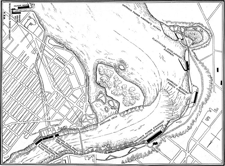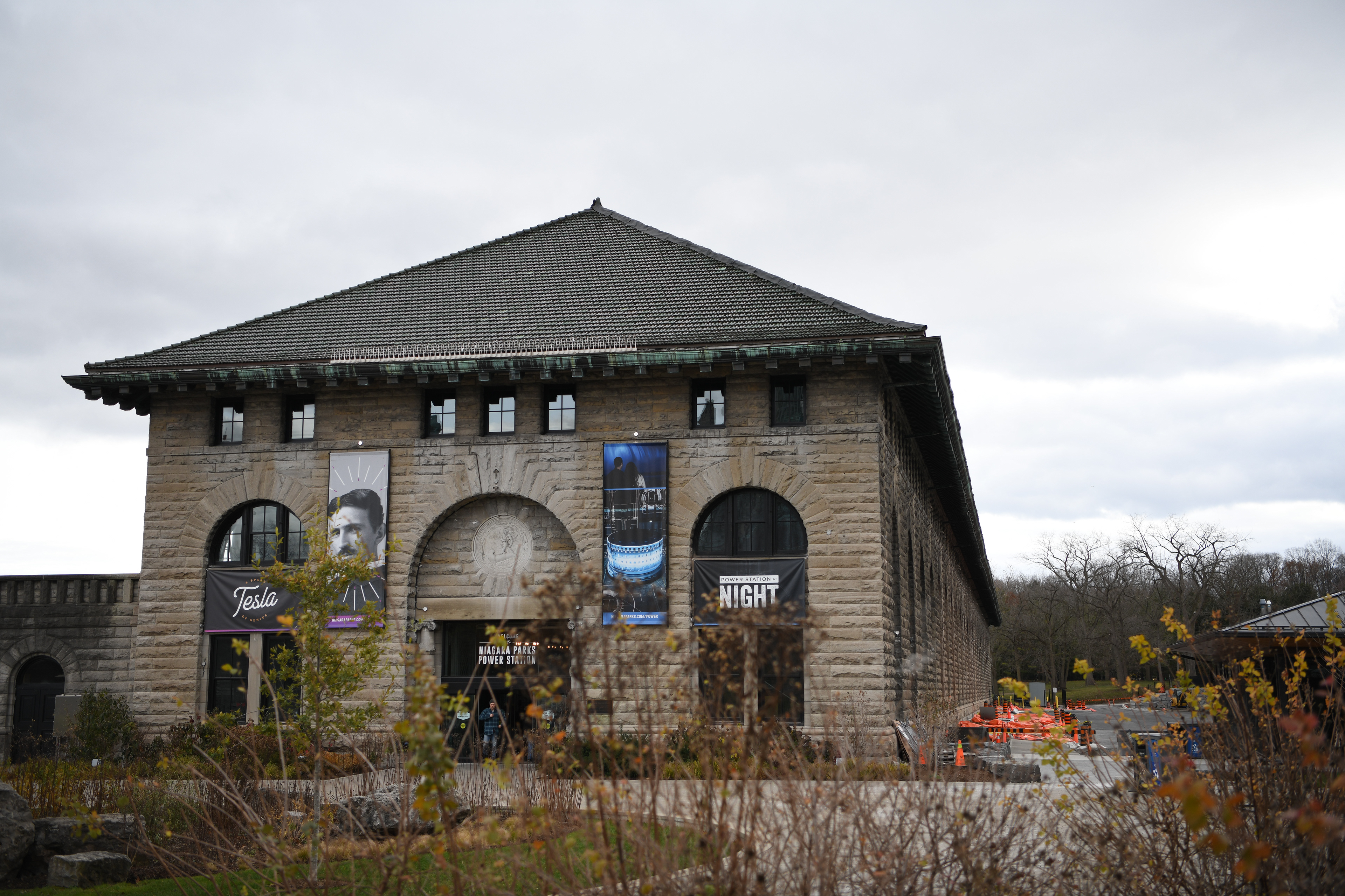
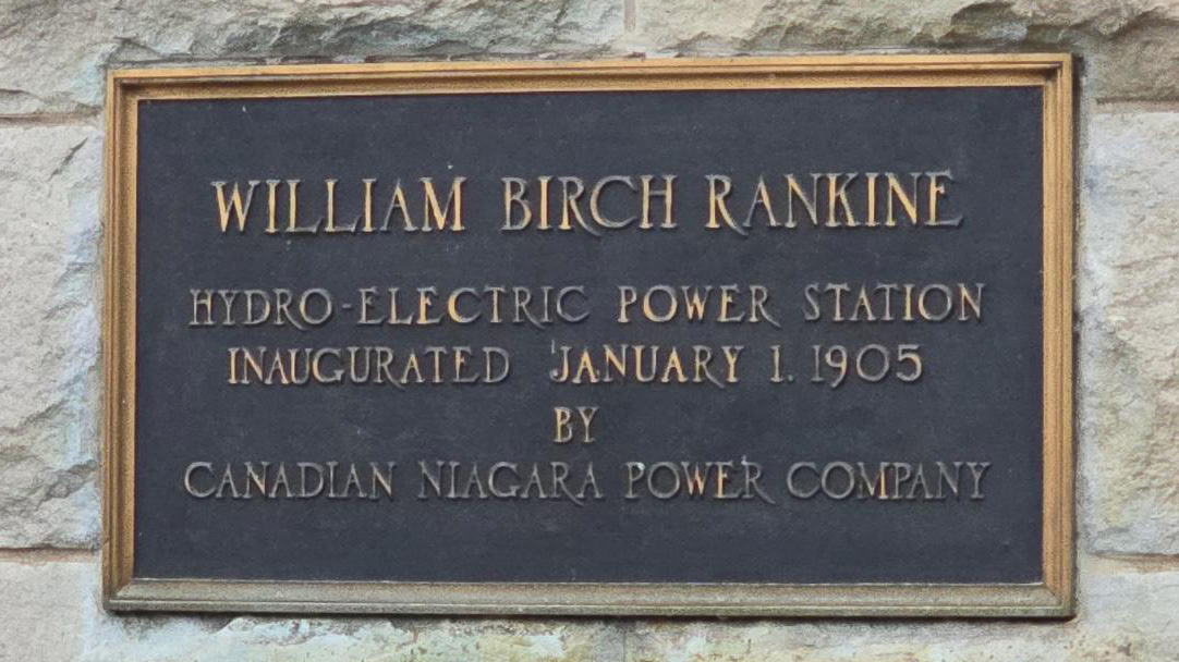
The Rankine Generating station is located just above the Horseshoe Falls in Canada.
Construction began in May of 1901 and two units were placed in service in January 1905.
The roof was made of Terracotta tiles.
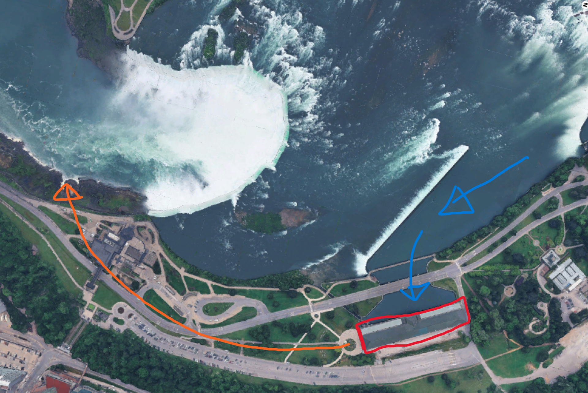
Outlined in red is the Rankine Generating Station. Water was diverted from the Niagara River, processed through the station and discharged through the Tailrace tunnel (orange) 180 feet underground and discharged back into the Niagara river below the horseshoe falls.
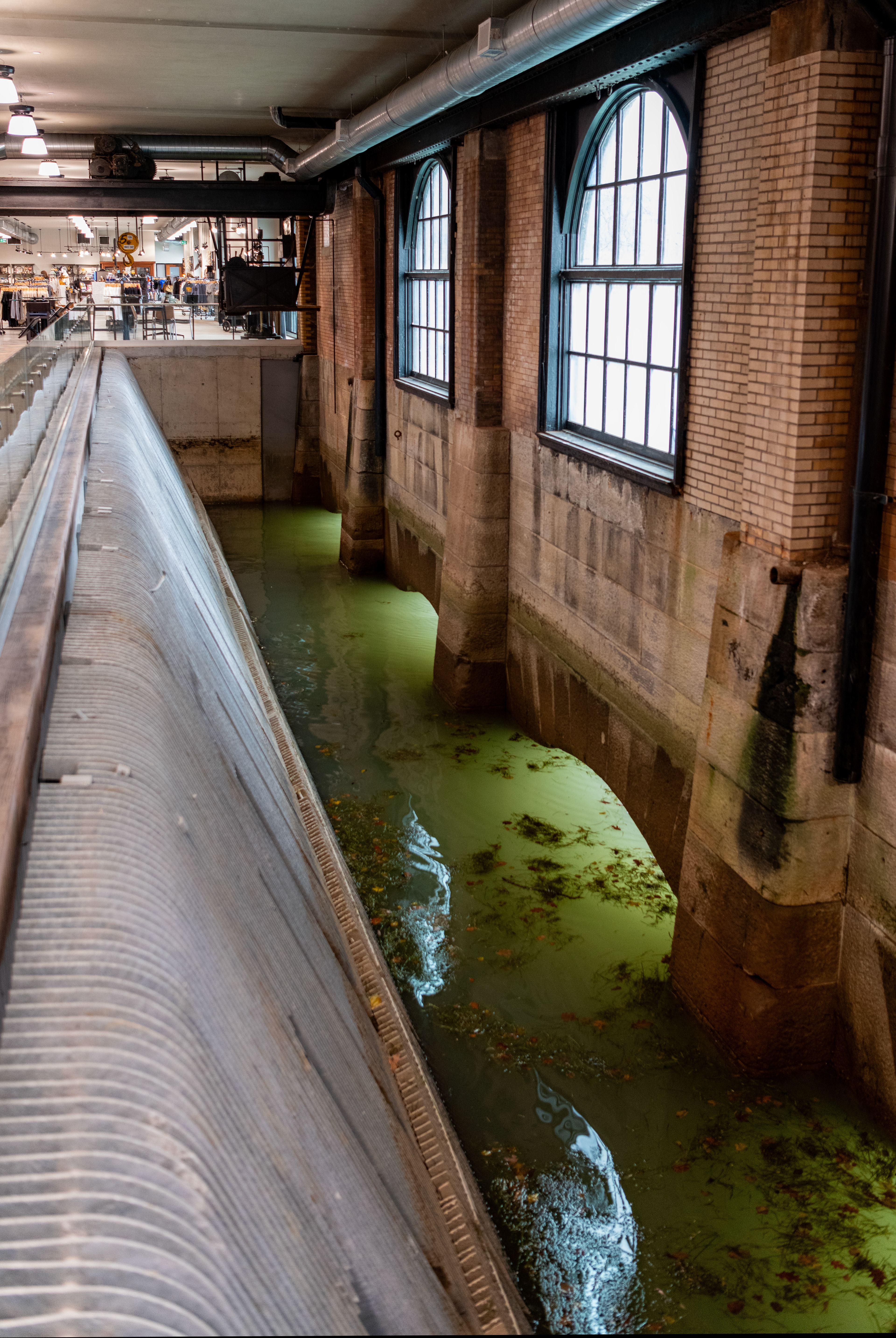
This is the Intake Forebay which brings water in from the Niagara River upstream of Niagara Falls and runs it through bar screens as pictured here. Originally this forebay and screens would have ran the entire length of the building, allowing intake water for each unit. The overhead crane was used to raise the screens, allowing them to be cleaned. Water would flow through the bars on the left and continue to each unit.
These bars would prevent large debris and ice from entering the unit and damaging the turbine & other components.
Pictured here is a Head-Gate. Each Unit has it's own Head-Gate. The water from the forebay (on the other side of this wall) would flow under the floor here and to the Unit (behind me). The Head-Gate was a large wall which would be lowered into the area inside the yellow box on the floor. This gate would stop the flow of water to the Unit allowing for maintenance to take place.
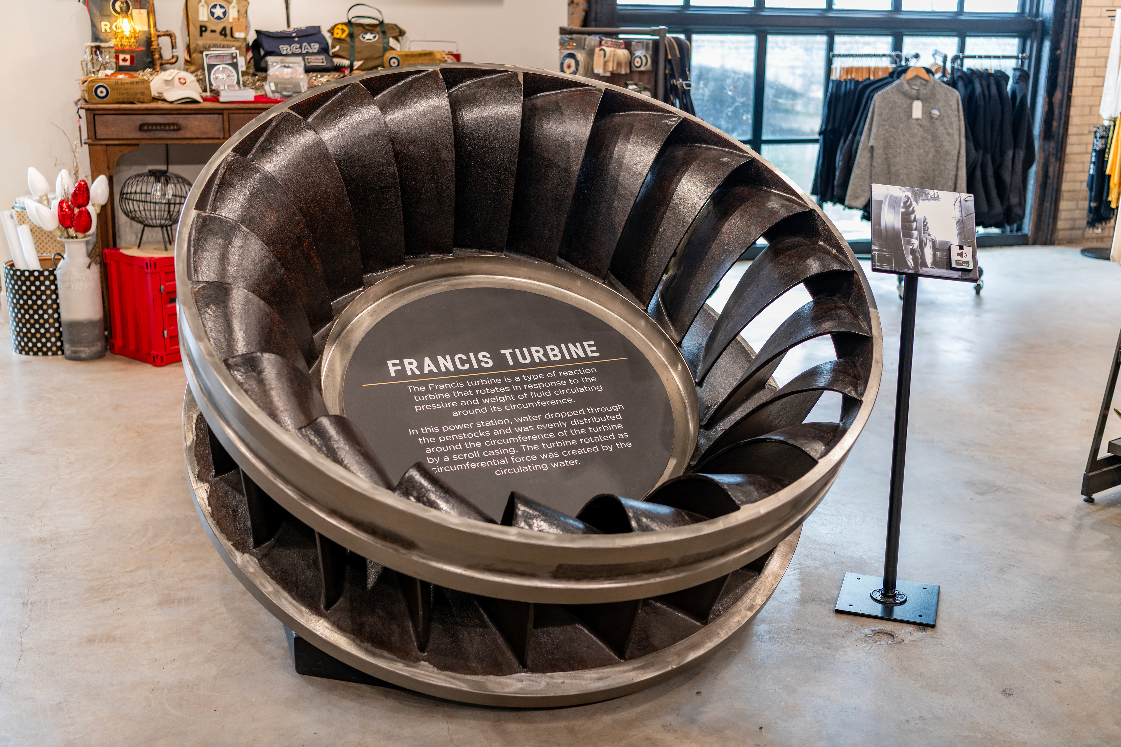
The water which passes through the open Head-Gate would then flow down a large penstock (a vertical pipe) which would then enter the Turbine. The Turbine was located about 140 feet down (below the floor where im standing in the previous image). This image is a spare Turbine at the station. Due to the large height difference, water would flow down the penstock and rotate this turbine.
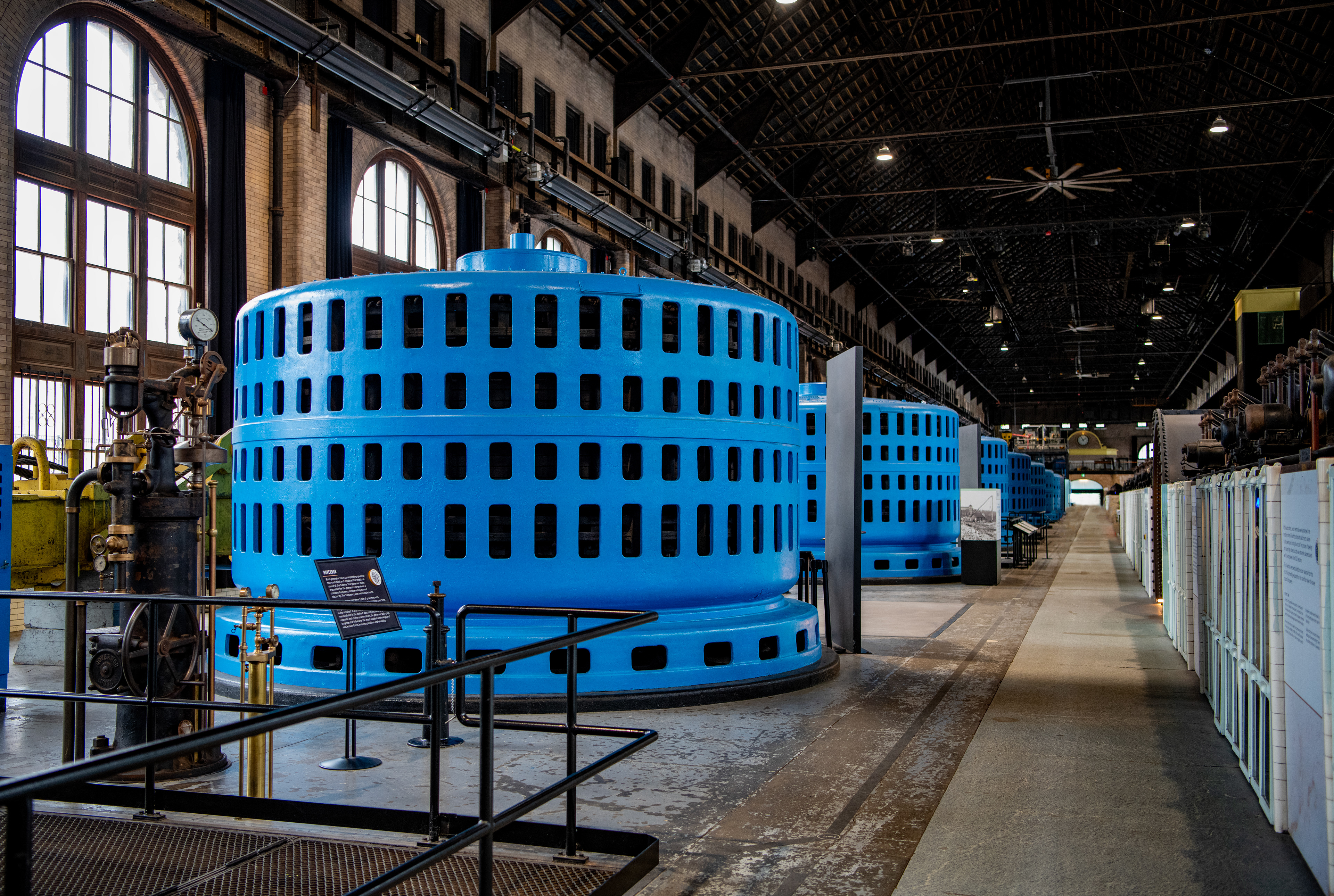
11 Unit Alternator Hall at the Rankine Generating Station.
A Turbine is located about 140 feet below this Alternator (aka Generator). The Turbine was connected by a very long shaft (and bearings) to this Alternator. The spinning Turbine would also spin this Alternator, inducing a current in it's stator and thereby generating electricity. These generators rotated at 250rpm and generated 25Hz power for the area. The North American electrical grid would later be standardized for 60Hz power, however; these units were never upgraded. They continued to supply 25Hz power to steel mills in the Hamilton area which were still operating on 25Hz power until the early 2000's.
The original alternators were rated for 8,500KW. Each unit would output ~12,000 Volts which would then be stepped-up to 60,000 V via an output transformer.
Note that the oil circuit breakers are located in the white cabinets on the right of this image.
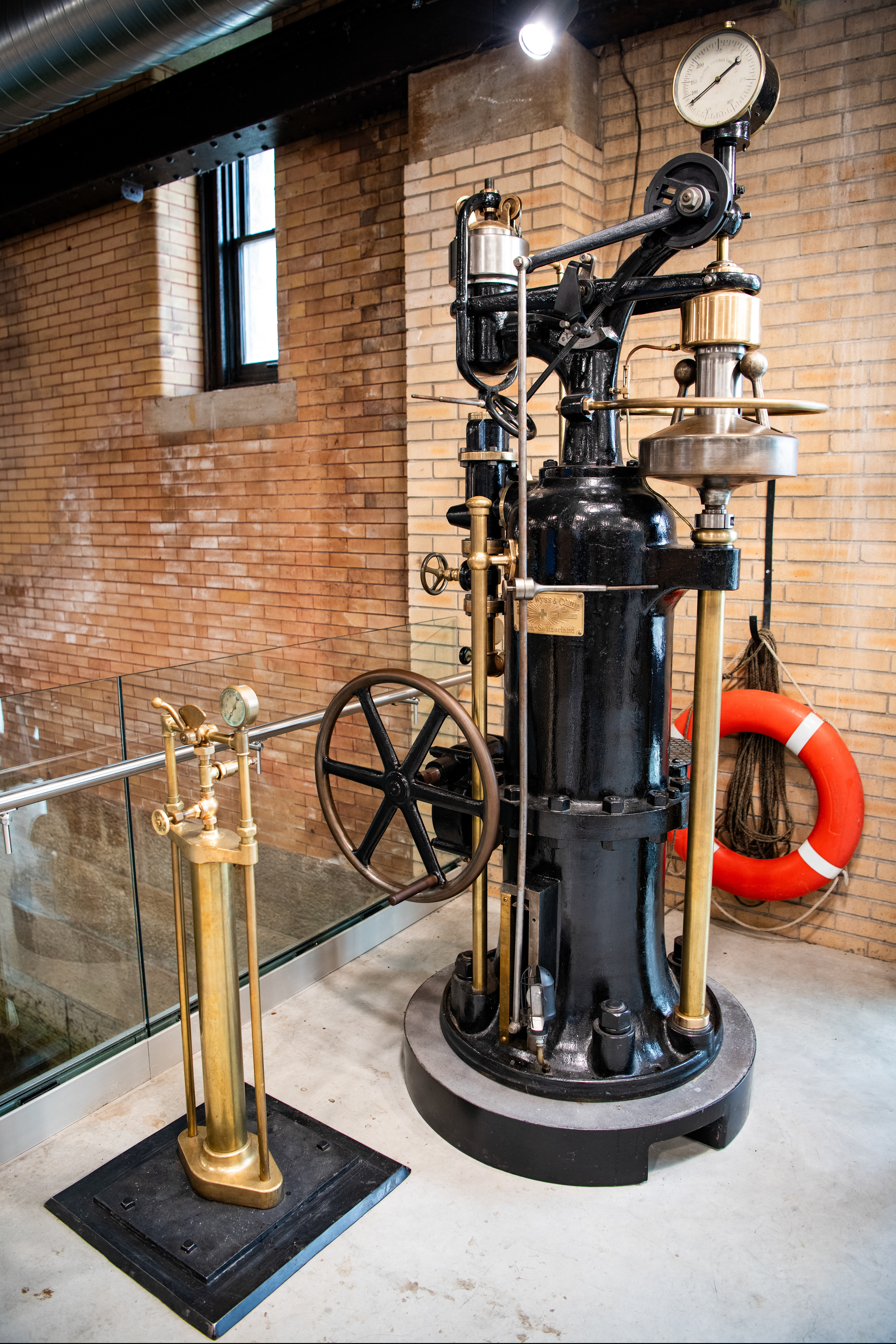
Original Fly-Ball governor made in Switzerland by Escher Wyss & Company. Air-Operated brake is on the left.
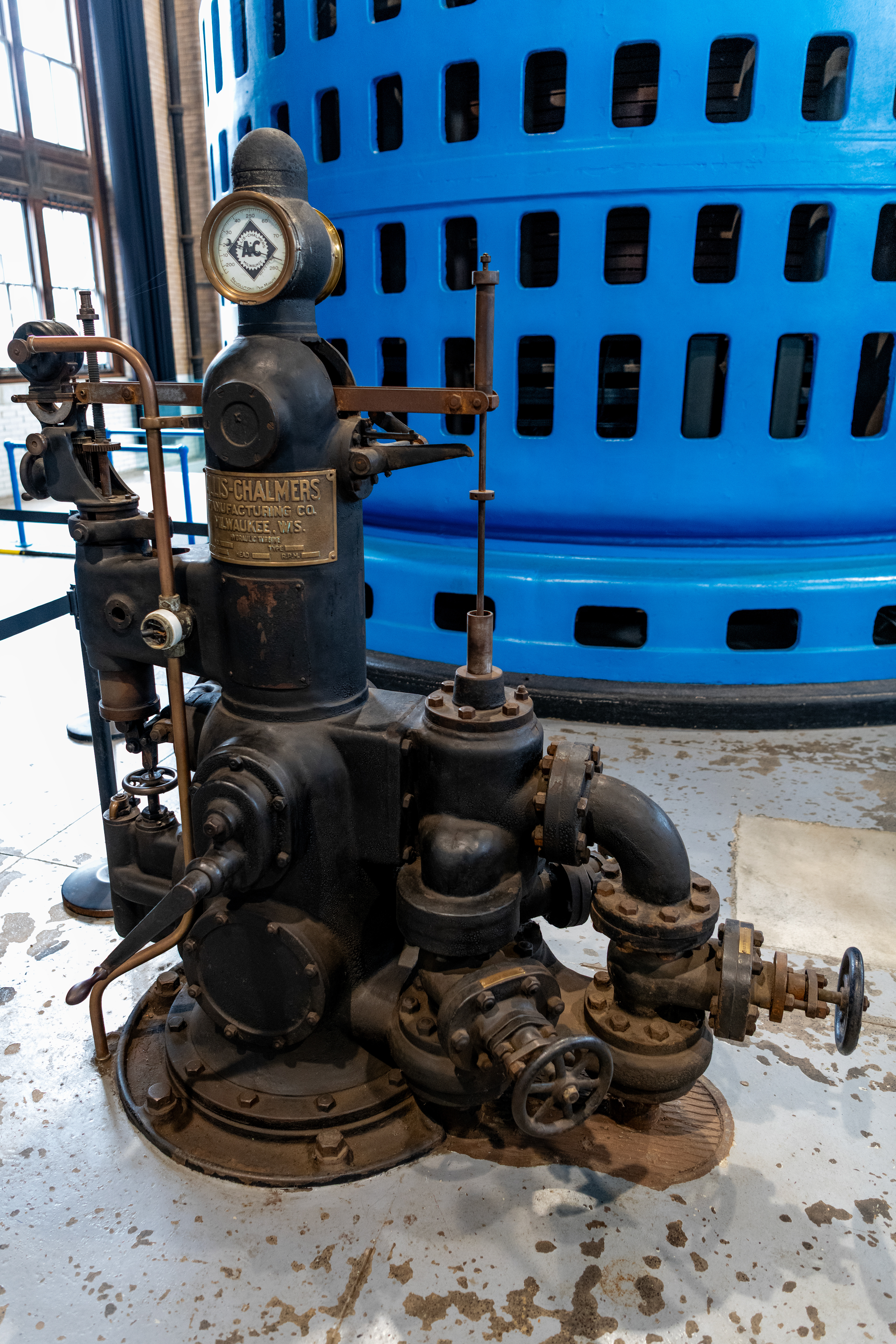
A governor valve was used at each unit to regulate the speed of the turbine. The governor was located after the head-gate and before the turbine.
Turbine speed is critical as it must remain at a constant 250rpm to supply reliable 25Hz electricity. The balls in the upper right would have assisted by self regulating turbine speed. If the balls rotate too fast, centrifugal force would send them outward and the linkages would cause the governor to throttle closed, thereby reducing water flow into the turbine and slowing it down. If the balls rotate too slow, the valve would be open further, allowing more water flow and thus more speed.
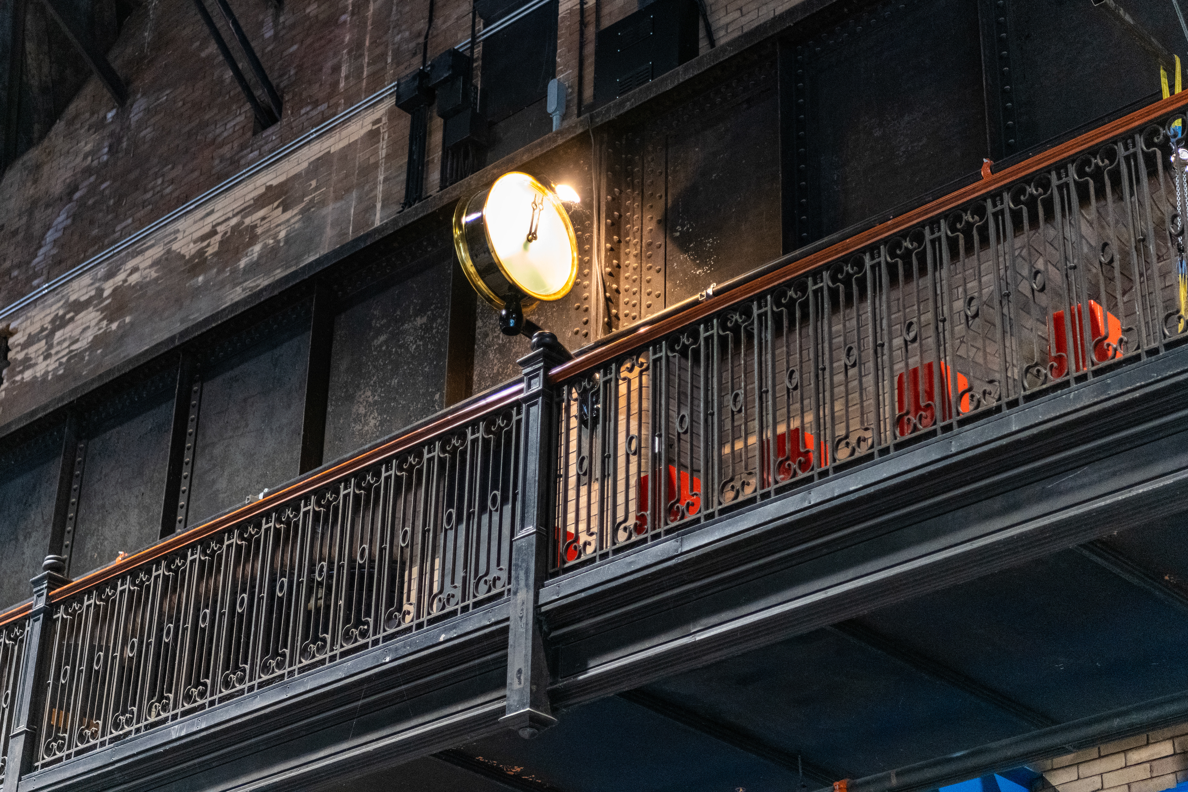
Pictured here is the original synchro-scope which would allow matching the generators alternating current to the electrical grids current prior to closing the output circuit breaker. As AC current cycles from positive voltage to negative voltage (in this case 25x a second or 25Hz) it is critical to ensure that the generator output sine-wave matches the grids sine-wave to prevent catastrophic generator damage when its output is connected to the grid.
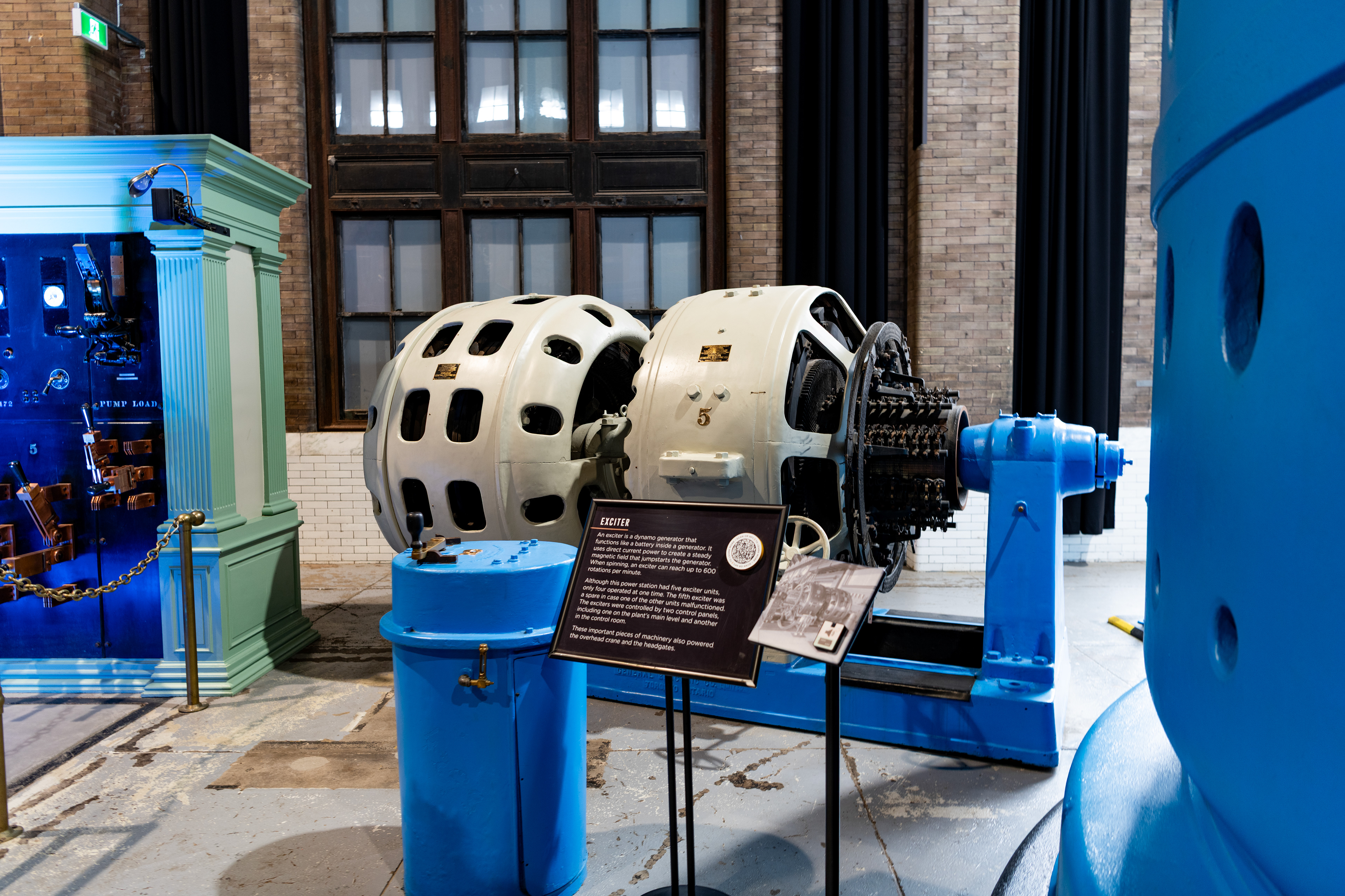
Pictured here is a generator Exciter which is used to apply a DC current to the Alternator rotor to allow control of output reactive power and to assist in starting alternator rotation.
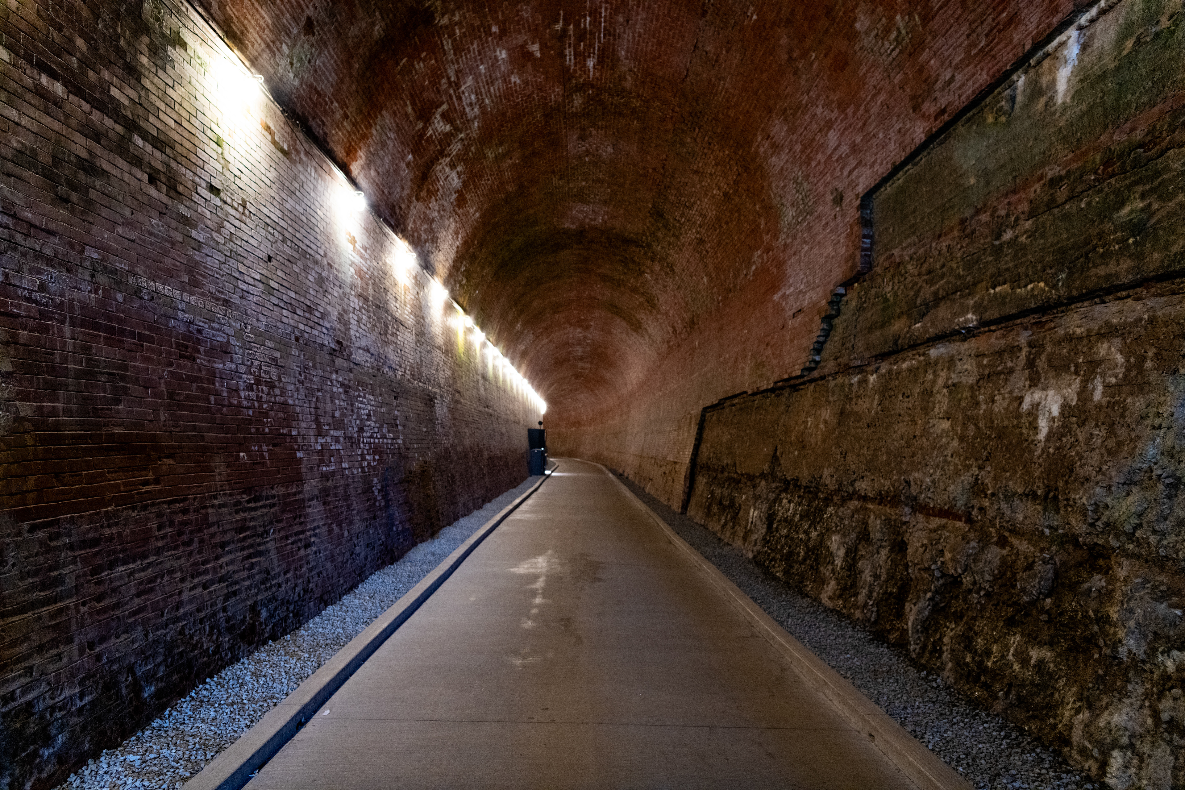
Water which has passed through the Turbine is then discharged into 1 common tailrace tunnel which would discharge the water back into the Niagara River downstream of the falls. This nearly half-mile long tunnel was man-made using over 5.7 million bricks.
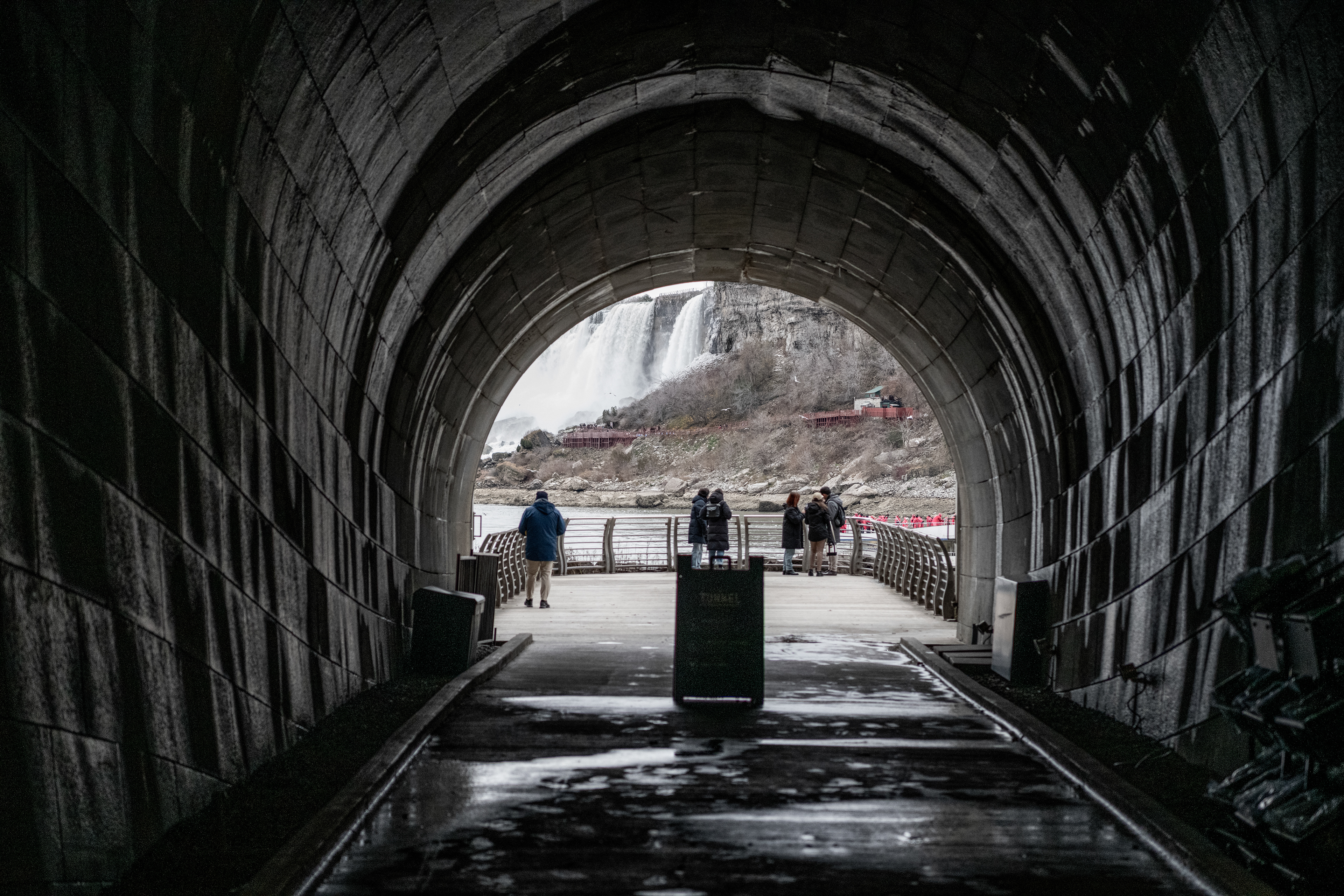
At the end of the half-mile long tailrace tunnel, water would be discharged accross from the US falls. The Canadian falls are just to the right.
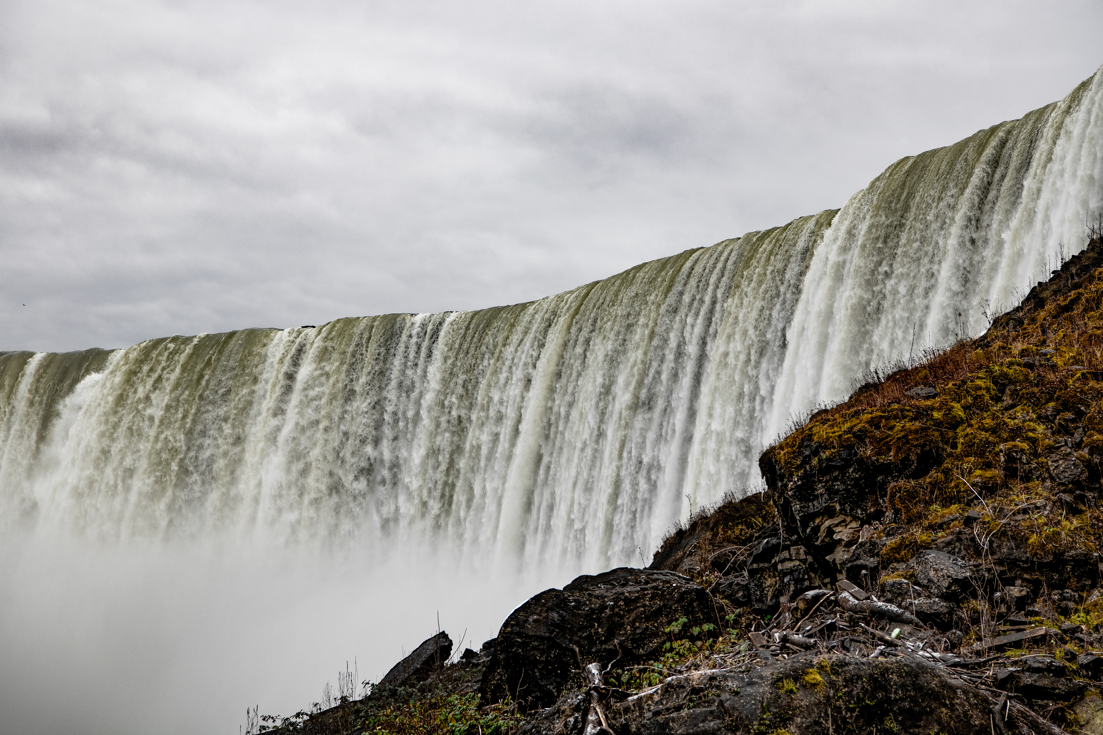
Looking to the right from the end of the tunnel at the Horseshoe Falls.
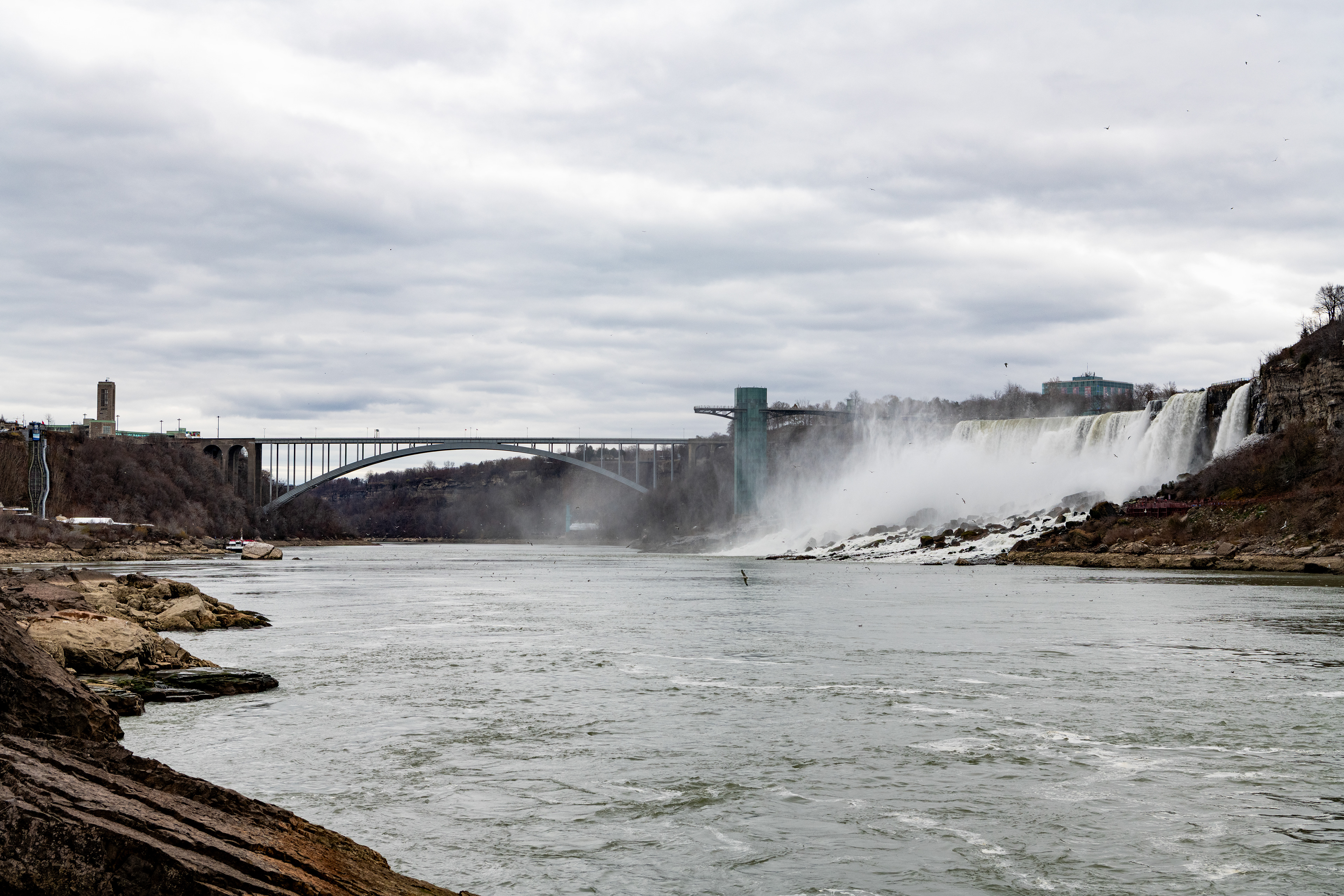
Looking downstream from the tailrace tunnel, US falls on the right.
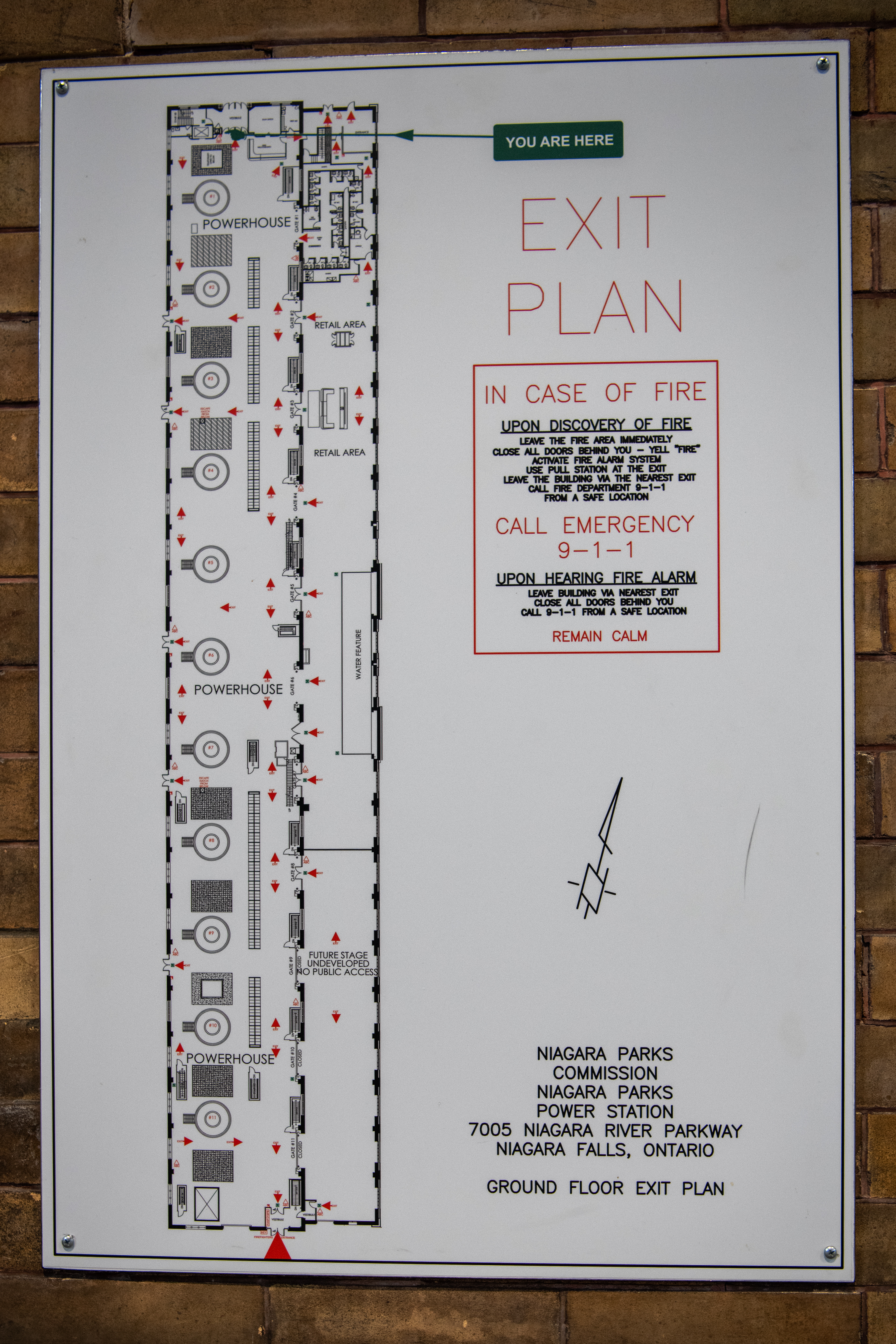
Current Museum floorplan.
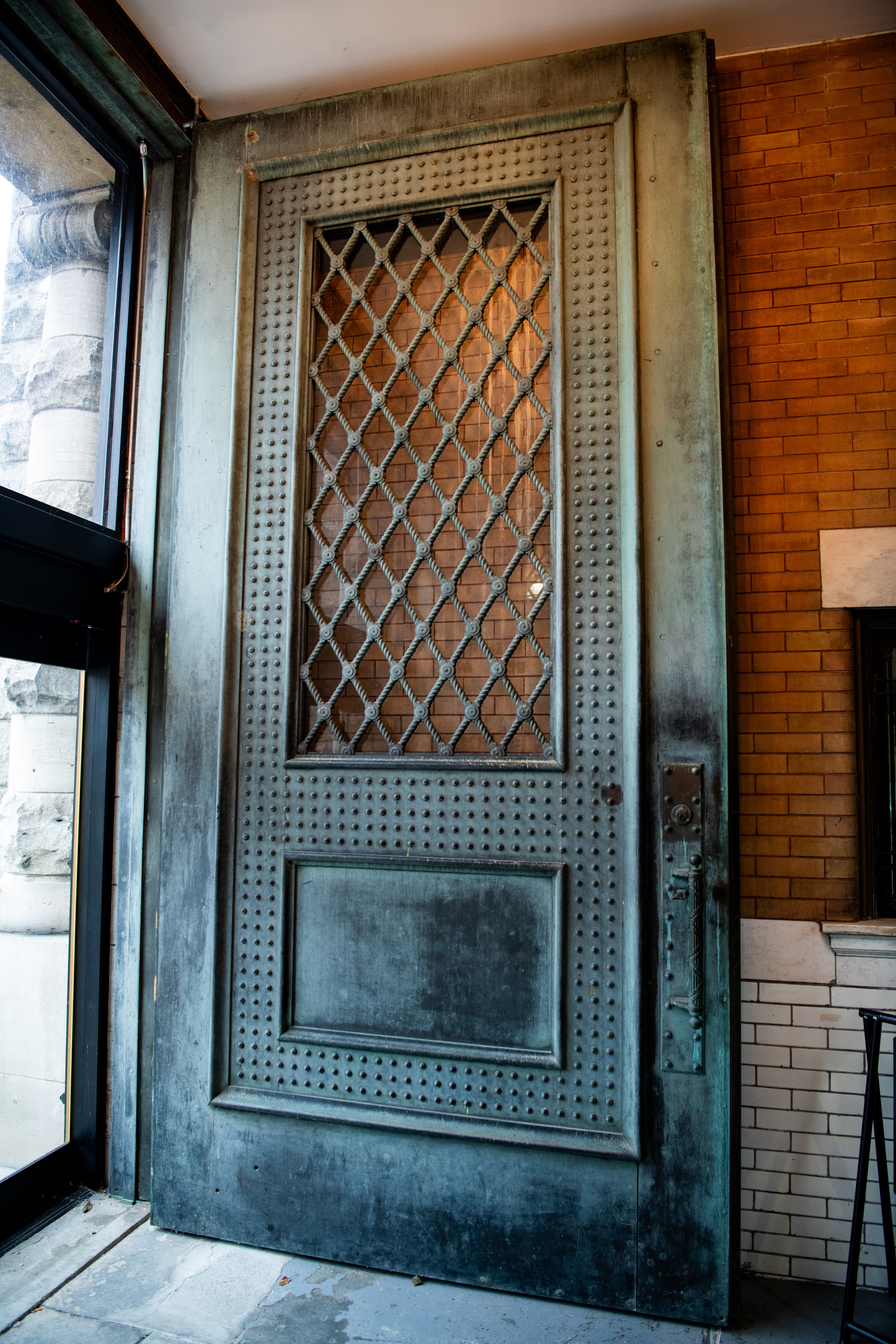
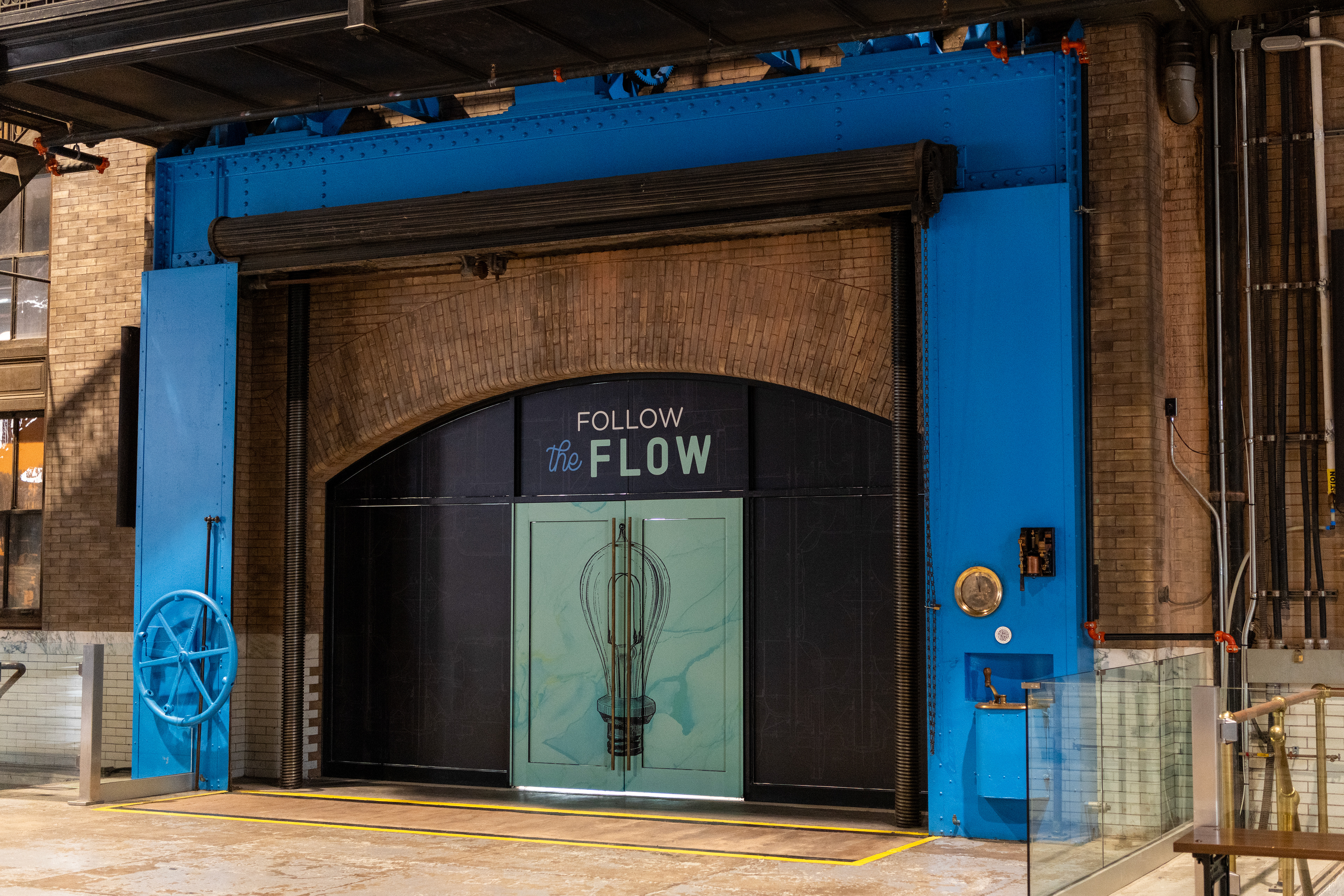
The main doors to the powerhouse were Brass and were polished daily, There was also Marble tiles in the powerhouse. Customers would have to enter the station to pay their electrical bills, so the building was finished with high-end finishing to help attract business.
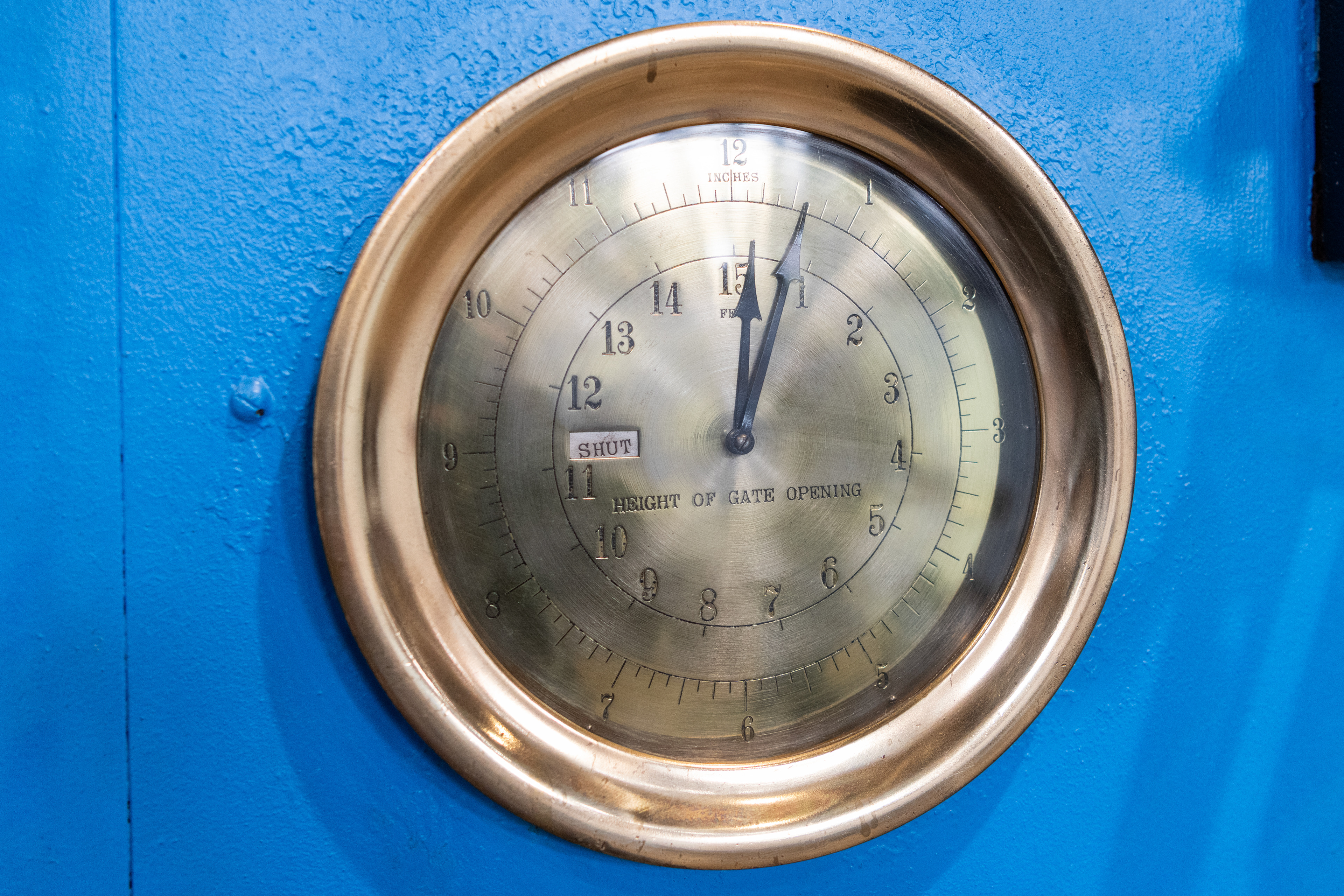
Original Brass Head-Gate gauge.
Later style governor which was less reliable than the earlier Swiss made design.